
Experiments
Safety Notice
Neither ASPIRE or any person involved with this website or the project is responsible for your personal safety or the safety of others due to your actions. Any loss of property or personal injury to you or others due to your actions is your sole responsibility.
Do not undertake any experiment or practical work without first fully understanding and implementing the protection and safe procedures that are required.
IF YOU DO NOT FEEL COMPETENT TO DO THE EXPERIMENT, THEN DON’T DO IT. LIKEWISE DO NOT DO ANY WORK IF YOU FEEL UNSAFE.
If you feel confident and wish to attempt any experiments, read our health and safety notes first.
Supersonic windtunnels
You may think that creating a supersonic flow for experiments is a hugely complex and expensive task which only government-funded professional laboratories can undertake. However, this is not true – creating small-scale supersonic flows only requires a compressor, an optional extra air-receiver and a carefully designed nozzle. These two videos illustrate just how easy this is:
All you actually need to generate a supersonic flow is a nozzle, hole or orifice with an inside to outside pressure ratio of greater than 1.9. For example, between your compressor and the ambient air. In other words, if ambient air-pressure is 1 bar, then the compressor needs to generate a pressure of greater than 1.9 bar – and most small compressors can usually supply up to 7 to 10 bar of pressure.
Now sure, the flows you can generate have fairly low Mach numbers – but actually the flow inside the engine is also fairly low – because it has been slowed down by the intake. For example, the flow in the mixing area of a Mach 5 (free-stream) scramjet is only about Mach 2.4.
And yes, the flow is only over a small area (up to a couple of cm). But again, this is sufficient to test pellet dynamics, flow around wedges and similar important aspects of the engine. Because the Reynold’s number of these flows is so high, with the exception of the boundary layer, small objects behave similarly to large ones – so you can build your test objects on a smaller scale.
Compressor and extra air-receiver photo:
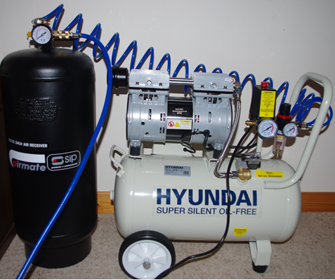
The general setup is shown below:
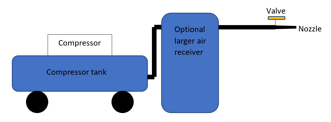
A setup like this will only give you a short burst of air before the pressure drops too low (a couple of seconds usually) and the larger the nozzle the shorter the burst. This means that experiments have to be short in duration and it’s often best to try and control the setup electronically if possible.
By careful design and production of the test area (the nozzle and its associated parts) using, for example, 3D printing, much more performance can be squeezed out of the system. The following file explains the options and a more technical view of these can be researched in Anderson’s books listed in the further reading page:
It is also worth searching for “supersonic windtunnels” on Youtube and in Google to get an overview and design information.
This Excel spreadsheet allows you to find parameters for these.
NASA have several pages about windtunnel nozzles and also some useful JAVA simulators for these. However, you need a JAVA enabled browser or Java IDE to view and use these (some modern browsers like Microsoft Edge won’t run JAVA for security reasons):
Although you don’t need it (you can use a simple straight or parabolic curve – or copy an existing design profile), you can use the method of characteristics to design or more optimal or sophisticated diverging section if you wish to – how this works is explained in this document
Once you have your test setup or tunnel is up and running you can build a visualisation system or take measurements in the flow. These can range from simple shadowgraph systems to very complex optical setups.
Some more advanced design techniques are available here.
What all this is for?
Finally, what can you do with all this? Well, we’d like to know about the dynamics of the air and fuel in the system - how does the air flow around the moving wedges, how do the pellets react and accelerate when the flow impinges on them, how do they distribute themselves though the flow? Some simple experiments and questions to get you started are listed in this document.
If you are experimenting with the dynamics around wedges, you might be interested in the information below – which gives information on the Mach-numbers of the flow around the wedges: